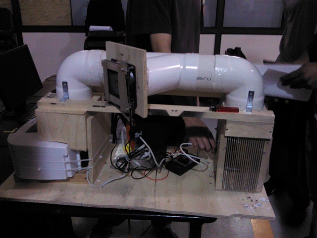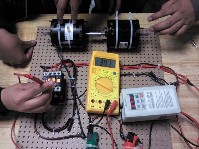

Un motor eléctrico jaula de ardilla se convierte en generador eléctrico cuando el campo magnético inducido en el rotor supera la velocidad de giro del campo magnético del estator que se encuentra a 50/60Hz
Práctica desarrollada en IPN - ESIME Azc. Elaborado por: A.
Isidro, A.L. Ponce, O. Sosa, J. Zamudio y M. A. Ramírez en la Clase de Máquinas Eléctricas 4mm2/12-2012, IM

Recently, Boeing began using model-based definition (MBD) to see if it could improve productivity and reduce time to market.
MBD is a method of annotating computer-aided design models with geometric and tolerancing information that allows engineers to draw directly onto a 3-D model. It shows promise for improving and accelerating design, manufacturing, and inspection processes.
A group of researchers from École Polytechnique Montréal and the University of Quebec École de Technologie Supérieure set out to investigate the feasibility of MBD's one day taking the place of 2-D engineering drawings used throughout industry today.
Traditional engineering drawings are still essential for capturing and distributing non-geometric information at most companies today, notes Louis Rivest, research leader. He stressed they are looking at the feasibility of eliminating the 2-D drawings, not eliminating paper itself.

From ASME Y14.41: figures illustrate (from top) a solid modelwith all annotation displayed, with one type of annotation displayed, and with selected annotation displayed.
View largerBased on Standards
For a long time, the industry has been moving toward tolerancing solid models rather than two-dimensional models. MBD has been rooted in the 2003 ASME Standard Y14.41-2003 Digital Product Definition Data Practices, which sets requirements for CAD software developers to follow for tolerances, dimensional data, and other digital design annotations on 3-D solid models.
Tolerancing is showing dimensions and tolerances on a model. Prior to this standard, nothing in the industry dealt with displaying tolerancing on 3-D models, mentions Alex Krulikowski, chairman of the Committee on Solid Model Tolerancing that helped spearhead the standard.
The standard addresses the depiction of tolerances in model-viewing mode: rotating the model rotates the tolerances with it. It also ensures that engineers and manufacturers are communicating tolerancing in an accepted way, so a user knows how to find them on a drawing, how to interpret them and read them, Krulikowski explained.
Unique Implementation
With the tolerancing standard in effect, the researchers interviewed 34 representatives from two major Canadian aerospace manufacturing companies and found that the move away from 2-D drawings is feasible for most industries, though it faces some barriers that could be addressed through simple technology changes.
How actual engineering, manufacturing, and inspection processes would need to be redesigned if MBD, rather than 2-D drawings, were to be used depends on the adopting industry. "Releasing the engineering drawing is a process; each company has thousands of processes defined. We couldn't address them all. We concentrated on what would need to be done to make the best use of MBD data and get rid of engineering drawings." Rivest said.

Digital Product Definition Data Practices specifies the form for entering queries ... as in these examples, for a question of size tolerance (above) and geometric tolerance (below).
View largerSimplified Viewing
Industry-wide, when 3-D models replace engineering drawings, downstream users who currently rely on these drawings would need another method for communicating product dimensioning and tolerancing data. Many non-engineer users have no access to or familiarity with CAD; a lightweight format is needed to communicate this information, said researcher Virgilio Quintana.
Viewer programs convert MBD data from different CAD applications to lightweight format files, containing the model along with dimensions, tolerances, annotations, management information, and revision history. These files could be readily opened, read, and understood by users without CAD experience, he explained.
Inspection Aid
According to Rivest, inspection processes would be quicker and potentially even more accurate by adopting the MBD format. Time savings would occur by minimizing operator inputs required during programming and running coordinate measurement machine inspections since model-based software would compare parts against tolerances contained within the CAD model itself rather than from engineering drawings whose tolerances traditionally had to be derived from 3-D data.
The accuracy and integrity of the inspection process would be improved by the software's ability to check contour and hold positions as well as constraints, such as flatness, concentricity, and angularity. Model-based software also enables automated inspection routines, which ensures parts are inspected in the same way, in the same places, and with the correct tolerances every time, wrote Rivest, Quintana, and others in Computers in Industry (March 2010).
A Matter of Trust
Overall, the Canadian researchers found evidence that moving away from 2-D drawings is now feasible for most industries, and does offer real benefits. Some barriers could be addressed with simple technology, but some are cultural and difficult to change.
People still aren't fully convinced about MBD, Quintana said. It's hard for them to trust an electronic file versus a printed 2-D drawing kept in a safe place. Still, they may have to justify making the changes sooner rather than later to supply or compete with bigger companies who are early adopters.
[Adapted from "Digital Tolerance," by Jean Thilmany, Associate Editor, Mechanical Engineering, July 2010.]


Recent Comments